The 160 m. Propagation Mystery – part 2
Long distance propagation
In November 2016 Carl Luetzelschwab, K9LA, published on his website K9LA a very interesting study on the VK9LL Dxpedition by Tomas VK2CCC in September 2013and based on my log analysis and graph at that time and published on this page vk9ll---2013.htm.
On Carl’s article http://k9la.us/Nov16_A_Look_at_the_160-Meter_QSOs_of_VK9LL.pdf we read:
“One of the comments that Tomas made after the DXpedition was that he didn’t understand why he had so many more QSOs with Europe than North America. He made 191 European 160-Meter QSOs but only 54 North American QSOs. That’s a good comment from Tomas for three reasons:
1) Depending on the country, the path to Europe is 16,000 – 17,000 km, whereas the path to North America is 11,000 – 14,000 km. With a shorter path, North America should have dominated due to less ionospheric absorption and less ground reflection loss.
2) The path to Europe had about two hours of common darkness (this is the time the entire path between VK9LL and Europe was in darkness – which is where 160m RF needs to be). The path to the West Coast of North America offered about six and a half hours of common darkness. With more hours of common darkness, North America should have dominated due to much more available time.
3) The path to Europe at the VK9LL end appears to have a terrain issue, but the path to North America has an open horizon. Digging deeper by looking at a terrain map of Lord Howe Island indicates that the hills to the northwest of VK9LL on the heading to Europe are about 2.5 km away and go up to 147 meters. Doing a little math says the hills would block RF below about 3.5 degrees. I don’t see that as a problem on 160-Meters.
Reason #1 above gives us a clue as to what may have been happening. Indeed, the farther the distance the more the loss (absorption and ground reflection) and thus less signal strength. This assumes propagation is via multi-hop – successive refractions and reflections between the ionosphere and ground. If this doesn’t happen, then maybe some other mode is involved.
Multi-hop propagation
A simple calculation shows why multi-hop is a problem. We can estimate the received signal power (Pr in dBm) with the following formula:
Pr = Pt + Gt + Gr – FSPL – abs – gnd refl
Pt is the transmit power in dBm, Gt is the transmit antenna gain in dBi, Gr is the receive antenna gain in dBi, FSPL is the free space path loss (spherical spreading of the wave) in dB, abs is the total ionospheric absorption in dB and gnd refl is the total ground reflection loss in dB.
Pt, the transmitted power is 50 dBm for 100 watts, 60 dBm for 1 KW, 61,8 dBm for 1500 W and 70 dBm for 10 KW
Gt, the TX antenna gain is usually zero on 160 meters
Gr, the receive antenna gain usually is zero, but can be quite negative (- 50 dB with small loops)
FSPL, the Free Space Path Loss is the simple inverse distance dispersion of the energy in the space (total effective travel up and down) and is calculated: FSPL = [32,5 + 20 * Log (d) + 20 * Log (f)]. To avoid logarithmic calculations these tables may be useful:
|
Distance Km. |
20*Log (d) = loss dB |
Frequency MHz |
20*Log(f) = loss dB |
|
10 |
20 |
1,8 |
5 |
|
100 |
40 |
3,5 |
11 |
|
1000 |
60 |
7 |
17 |
|
3000 |
70 |
14 |
23 |
|
10000 |
80 |
21 |
26 |
|
30000 |
90 |
28 |
29 |
Abs, is the sum of all the ionospheric absorption losses and depends on the sunspot number, the frequency of operation, the gyro-frequency, the radiation angle and the zenith angle at each refraction point. It can be calculated with this spreadsheet, but generally is between 5 and 8 decibels for every hop.
Gnd refl, is the sum of all the ground reflection losses; they depend on the ground type and the incidence angle of the wave; can be calculated with this table:
|
For each reflection over |
Incidence angle |
Loss in dB |
Incidence angle |
Loss in dB |
|
Sea |
Low |
0,5 |
High |
0,2 |
|
Ground |
Low |
3 |
High |
5 |
|
Snow/Ice |
Low |
6 |
High |
8 |
Let’s make an estimate for an 11,000 km path (the shortest path to North America from VK9LL). This will take 6 hops since the maximum hop length on 160-Meters is about 2000 km – regardless of whether it’s an E hop or an F hop. With Pt = 50 (VK9LL ran 100 Watts), Gt and Gr = 0, FSPL = 119, abs = 42 (7 dB per hop for 6 hops) and gnd refl = 10, we get Pr = -121 dBm.
That’s certainly above the MDS (minimum discernible signal) of a typical receiver (which is around -135 dBm), so all is okay – right? No, it’s not. Unfortunately, external noise (both manmade and atmospheric) limits our receive performance on 160-Meters to around -103 dBm in a quiet rural environment.. Even worse if we live in a more noisy environment (man-made noise on 160m. in a residential area is -83 dBm) as shown in the graphic below.
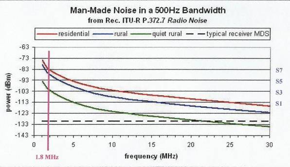
An acceptable positive Signal to Noise Ratio - S.N.R. is what we need and, in this case, it is -121 dBm -103 dBm, = -18 dB, not enough to pull out at the receiver.
Doing some more math with Pt = 61.8 dBm (1500 Watts) the SNR raises to -6 dB and suggests that 10,000 km or so is about the maximum distance for multi-hop on 160-Meters. Of course using 4-Squares on both ends would extend this a bit – but not by much. The other mode is ducting.
Ducting
For paths similar in distance to that between VK9LL and Europe, one needs to consider ducting in the nighttime electron density valley that exists between the E region peak and the lower F region. In order for a signal to get into a duct, it has to have a high enough elevation angle to get through the E region, but not so high as to not be refracted back down from the lower F region – and then it needs to be refracted back up again by the E region.
Working with a ray racing program – Proplab Pro V3 from Solar Terrestrial Dispatch - on 160m hints that there are three ranges of elevation angles on 160-Meters that give us three different modes. The following figure depicts this concept for a representative nighttime path on this band.
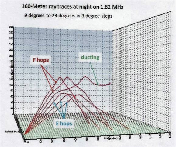
In this example, rays are traced from 9 degrees to 24 degrees in 3 degree steps. Elevation angles up to 15 degrees result in E hops. Elevation angles above 21 degrees result in F hops. Between 15 and 21 degrees we see the start of a ducted mode with successive refractions between the E region peak and the lower F region. The ducted mode results in no transits through the absorbing region (Layer D) to add loss and no ground reflections to add loss.
The mechanics of ducting may not be the same for different headings out of a given location. The underlying reason is likely the electron density of the E region and that of the lower F region. Both of these would determine if an elevation angle could get through the E region but still be refracted back down from the lower F region and back up again by the E region.
On our side, regardless of the program simulations, it is not possible to know which is the best angle of elevation to enter the duct and, in any case, it’s not easy to vary the angle of radiation of an antenna on 160 meters, as it could be on 6 meters. It’s depending on the antenna type but, to be within the best angle is mainly a matter of luck. The antenna does not throw an arrow, which would hit or not hit a target: its radiation lobe is always broad, at a wide range of angles. However, we know that already 3 dB less represent a reduction of 50% of the power, both in transmission and in reception, for which we would like the most possible of our radiated energy be channeled towards our DX target.
How many times did you hear a station with a modest antenna in a modest location, not far from you, working a DX that you were not copying at all, despite your Beverages? Do not get angry and do not be envious, or even worse, do not blame the lucky one to use a remote SDR on another continent (although unfortunately this happens!). On that occasion, the elevation angle of his antenna was among those favored to enter (or exit) the "ducting", while a wonderful Beverage showed a deep "null" right there. (Especially at sunrise it happens that the DX signals arrive with high angle, and a low dipole receives them better than a Beverage). The same applies also for horizontal directivity: quite often long distance signals arriving via "ducting" are skewed up to 45 or 60 degrees (generally towards the south) from their azimuthal direction: even in this case a very long and efficient Beverage may happens to be out of the direction where the signal actually comes.
In any case "ducting" is the most responsible ways of the "Spotlight propagation" which favors, with very strong signals, some limited areas, while a few hundred km. away nothing is heard. 160 meters require a lot of patience, and, sooner or later, the favorable moment of the "spotlight" comes to everyone, just be there!
January 16, 2017 – Luis IV3PRK