The Inverted L over FCP at HC1PF
A very efficient transmitting antenna in a very difficult environment
By Pierluigi “Luis” Mansutti – ex IV3PRK
Finally, after completing our new house, garden and family commitments, I could go back to my ham radio activity and start with antennas installation.
Unfortunately the realty was a bit different from what expected, with some new constraints and difficulties for 160 m. antennas. First of all, I was unable to find and put down a full ground radial system under the lawn. Than – we are in South America – it has been necessary to install an electric fence on top of the 2.5 m. high brick wall. The tuned elevated radials, as I had in Italy, should had coupled with these 180 m. long wires for sure – as it will be demonstrated – and thus my choice was to try the K2AV FCP system.
The vertical section
I carried from Italy the following aluminum tubes and the original design was something longer, but I had to shorten it for mechanical reasons, so these are the final dimensions of the vertical section.
|
|
|
Inverted L - final vert. dimensions |
|
|
|
Aluminium tubes bought |
|
|
|
|
|
|
|
diam./tichn. |
length |
Diam.est. |
Diam.int. |
Kg/mt. |
length |
cut to |
weigth Kg. |
|
65 x 5 |
6 |
65 |
55 |
2.545 |
2.50 |
2.50 |
6.36 |
|
|
isolator |
60 |
55 |
3.400 |
0.05 |
0.50 |
1.70 |
|
|
|
65 |
55 |
2.545 |
3.50 |
3.50 |
8.91 |
|
55 x 5 |
6 |
55 |
45 |
2.127 |
3.70 |
4.00 |
8.51 |
|
45 x 1,5 |
6 |
45 |
42 |
0.730 |
1.30 |
1.60 |
1.17 |
|
40 x 2 |
6 |
40 |
36 |
0.645 |
2.70 |
3.00 |
1.94 |
|
35 x 2 |
6 |
35 |
31 |
0.560 |
2.70 |
3.00 |
1.68 |
|
30 x 2 |
6 |
30 |
26 |
0.475 |
1.50 |
1.80 |
0.86 |
|
25 x 1,5 |
12 |
25 |
22 |
0.299 |
1.40 |
1.70 |
0.51 |
|
22 x 1,5 |
12 |
22 |
19 |
0.261 |
1.70 |
2.00 |
0.52 |
|
|
|
Total vertical ant. Length |
18.50 |
+ m. 2,5 m. base section |
21.00 |
|
|
|
|
|
|
Total weight Kg. |
32.15 |
So I began piercing the tubes and putting them together.
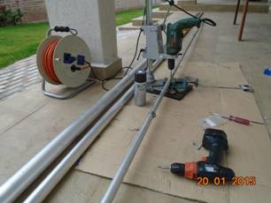
The lowest thick tube – 65 outside and 55 mm. inside diameter – was cut at 2.50 meters as a base section and inserted a piece of 60 mm. Delrin isolator. This is the point where the vertical radiator starts and the FCP counterpoise is connected.
Than I installed the base, built in my son’s workshop in Quito, with a gear winch and a 6 m. gin pole for a smooth rising:
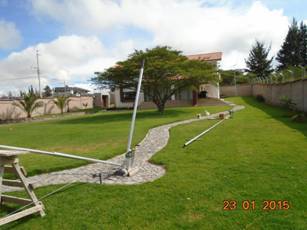
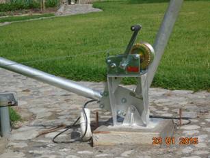
As expected on Saturday we were ready to raise it with the help of my good friend Rafael HC1TCD and his father.
That’s me with Rafael’s dad.
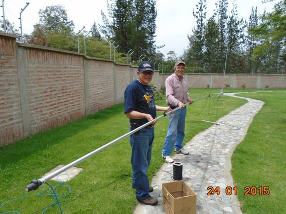
After the first rising attempt it has been necessary to cut some parts of the uppermost sections, so the total height was reduced from 24 to 21 meters.
As in all great occasions also the help of my wife Luisa was needed:
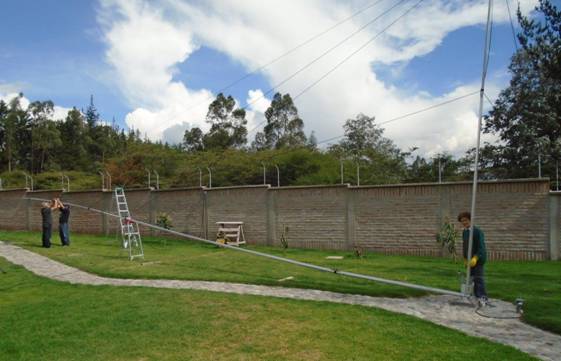
and finally the vertical section went up.
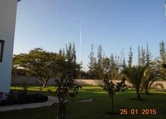
Lastly I installed the FCP counterpoise ( 50 m. of 2 mm. solid copper wire folded back on itself ) for a total length of 20 meters at 2.50 m. height, without any other radial or ground connection. I provided a lightning protection with two pieces of cutter shield with 1 mm. separation across the isolator. Inside the matching box I put a series/parallel combination of 24 ½ watts resistors of 10 Megaohm as static discharge.
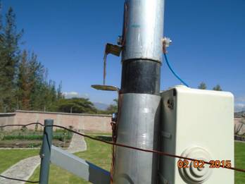
Tuning and pruning the horizontal wire
This has been the most difficult and time consuming process! I started with the horizontal wire of 28 m., for a total inverted L length of 47 meters, enough for shortening in search of the resonance as designed with Eznec. I built also the L-Network as calculated with TLW and checked with the .EZ model, but what a mess !
quite far from any kind of results.
So I had to ask for help to K2AV, the originator of the FCP system, and Guy has been really helpful. At first he said to forget all the EZ files because the results of a real antenna over an FCP are very different from the models and the only way to find a resonance is to look at the point where R is 50 ohms and than tune out the reactance.
But my readings were so far from the target and the antenna seemed to find a 50 ohm point below 1.500 khz or above 1.900 so I had to lengthen the horizontal wire to 32 m.; now the 50 ohm point went down around 1.850 and I began trying to tune out the reactance
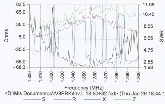
For two days I tried adding and subtracting mica capacitors with all the wide range of a Jennings 7-1000 pF vacuum capacitor, but no way to get rid of very odd reactance values.
So I decided to give up with the FCP and go back to the old tuned elevated radials. I cut two 42 m. radials and connected instead of the FCP. Even worse: the resistance value decreased around 20 and the reactance jumped higher. The elevated radials, much longer than the FCP were coupling much more with the electric fence.
By the way, Guy recommended me to make all the measurements directly at the antenna base, but that was impossible here due to strong BC nearby stations on 1.510 , 1.580 and 1.590 KHz ( 9+50 dB signals) which upset the readings of my AEA CIA HF analyzer; so all readings were made in the shack taking into consideration the feed line length, and they appeared quite stable and reliable.
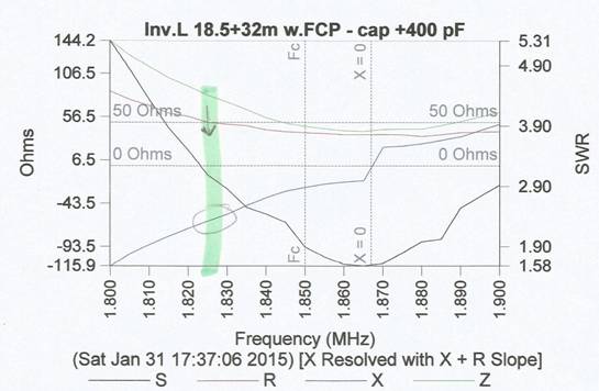
The next day I reconnected the FCP and began again with lower capacity values. The 50 ohm R point was where I wanted, on 1.825, but no way to tune out the reactance. .
After many other variations I came to the decision to further lengthen it and, after add, cut and try, I came out to 34.3 m., which means a total length of 52.8 meters, about ten meters longer than the expected quarter wave !
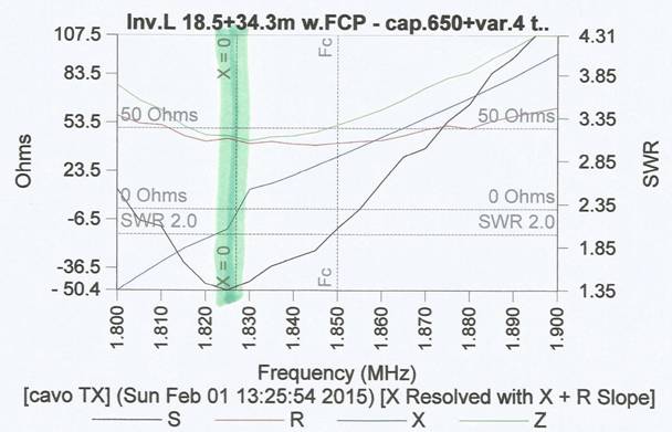
Now with one 650 pF mica capacitor paralleling the Jennings 7-1000 pF vacuum cap. I could finally tune out the reactance at 4 turns CCW (and there it’s extremely critical – just a few degrees of rotation takes it out.).
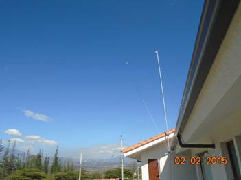
The last 2.30 m. of the horizontal wire had to be bended vertically.
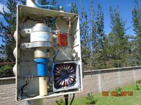
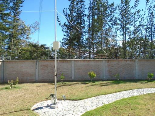
The vertical section is guyed with two sets of 5/16 “ and one set of 3/16” STI double braided polyester antenna rope bought from DX Engineering and this is the final picture showing the matching box at 2.50 m. height and the FCP wires counterpoise.
Despite the not perfect SWR – I always like the 1:1 – the performance “On the Air”of this antenna is outstanding. In a couple of days I worked a lot of NA and European stations with very good signal reports and I was unable to pull out many more calling me!
So I went back to EZNEC 5+ to model the real antenna and see what kind of pattern could be generated compared with the original classic Inverted L.
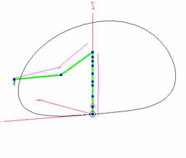
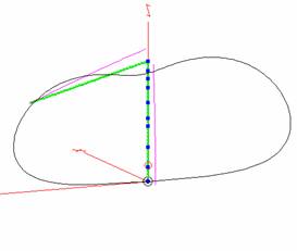
Inverted L at HC1FP Inverted L classic
Vertical section: 2.5 + 18.5 meters Vertical section: 2.5 + 18.5 meters
Horizontal wire: 32 + 2.3 meters Horizontal wire: 23 meters
Source data: 18.12+j 173.3 ohms Source data: 17 + j 2.3 ohms
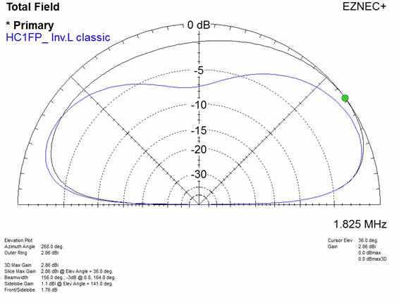
The results and the pattern agree with the study I had previously published on this page . At that time I was not aiming at such an high angle radiator, but the realty and local constraints took me there. Probably this kind of antenna works well only in this particular location, surrounded by a 183 m. electric fence, at 2.400 meter of altitude on the equator.
In any case the K2AV FCP system works great and gives everyone the possibility to put, also in a small lot, a very efficient antenna on 160 meters, thanks Guy !
Yesterday a direct strike destroyed the mica capacitor in parallel with the vacuum variable one. I substituted it with a close enough one but had to retune the whole system by lengthening also the horizontal wire until I reached a perfect match.
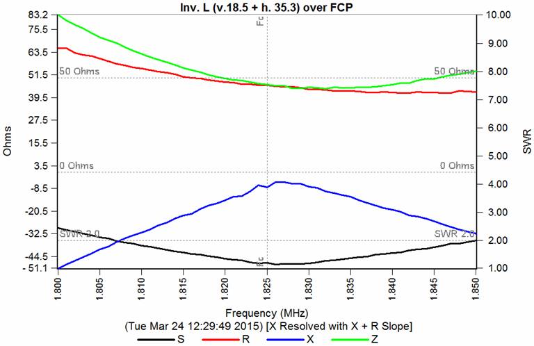
March 24, 2015
But in the following months the antenna collapsed three times due to sudden huge winds, always broken at the same weakest point (only 1.5 mm. thickness)
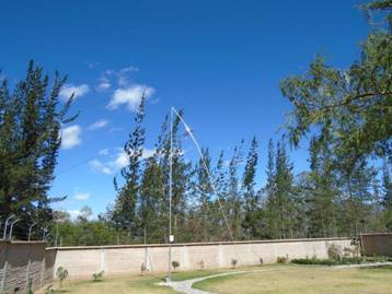
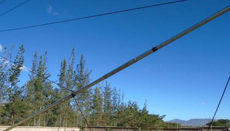
Promptly fixed and reinforced with what available, but the culprit was also a too weighting horizontal wire, so I changed it from #12 to #14, shorted one meter, better stretched without any sag, and tuned again. Here is better shown the FCP folded wire.
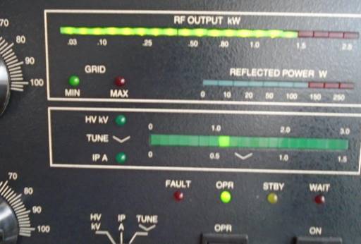
Now the SWR curve is a bit sharper, but lost the residual reactance with a perfect 1:1 on the segment of my interest. 1.5 KW output and zero watts reflected to make my Alpha 99 happy! But this is with 35 W of driving power, too much and lets me being heard better than what I can hear, so usually I keep it lower for about 800 W output.
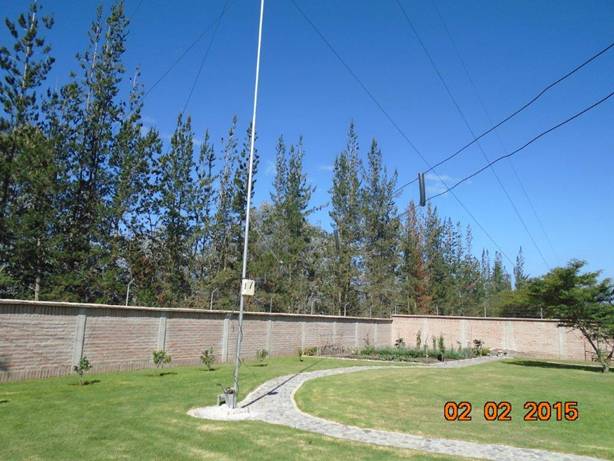
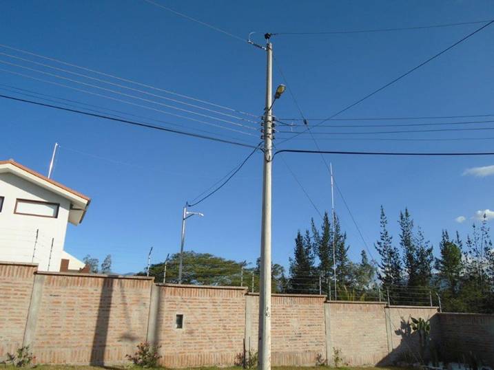
Anyway this last picture shows my environment and difficult way of living: surrounded by a 2.5 meter brick wall with 10 kV electric fence on top of it, control video cameras …and power lines (the higher one is 21.4 KV).
August 14, 2015 Luis HC1PF …soon will be back to IV3PRK
