The Reversible BOGs at HC1PF
At last achieved my best solution with receiving antennas
After trying every kind of receiving antenna I came to the conclusion that the only one functioning in my environment was a Beverage on ground, outside of my wall and electric fence and far from the power lines but, after a few days of happiness, a bulldozer entered in that terrain and….no more BOGs.
In spite of some days of disappointment and frustration, I didn’t give up and began to look for a new solution. My friend Gary, KD9SV, convinced me to try a small RBOG – Reverse Beverage on Ground - telling me that many Topbanders are happy with it: just a 200 feet of WD1-A wire and his ready to install system kit, now commercialized by DX Engineering.
Also Bruce, K1FZ, is a user of Beverages on ground antennas since many years and sells his own ready to install transformers.
Through the years I have been an happy buyer of the products from both them, but now it’s almost impossible to import stuff in this country, so I must do with what I carried in my container from Italy or what is available here.
But Gary and Bruce are old friend and genuine radio-amateurs, so provided me all the help and necessary advice.
The antenna wire
First of all it was necessary to find the suitable wire. My previous experiences in Italy with reversed Beverages using twisted pairs from CAT5 cable and later with RG58 coax on the ground were both negative.
Bruce, K1FZ said:
The WD-1A works well. There are those who do not like the wire because it has some resistance. But the published values are for one mile length. With 200 feet length it is not a problem. The wire is designed for war time conditions so it stands up well. It is OK for some twist in the 2 direction, two wire 200 feet wire, but not too many twist as received signal cancellation will take place.
Gary, KD9SV, sent me the following notes describing a telephone cable used in Finland, whose characteristics are similar to well known WD1-A
Twin lead telephone cable "killu" RF characteristics
In Finnish rural areas the subscriber lines were often made of twin lead cables. This twin lead line is black in color and it is called "Killu" in Finland. The internal part of the wire is iron and the surface is copper. The wires are covered by PE (Polyethylene, dielectric constant 2.3 - 2.4) solid plastic insulator which has good RF characteristics. Killu line is very suitable for RF use in amateur radio. It is very durable and you can get used cables easily free of charge. The cable is still available from some Finnish supliers.
Two types of the cable
MU 2x1.0 FeCu (wire diameter 1.0 mm, wire spacing approx 3.0 mm)
MU 2x1.4 FeCu (wire diameter 1.4 mm, wire spacing approx 3.8 mm)

Access network cables for aerial installation, called "Killu"
I measured the RF characterics of these cables. Here are the results:
Transmission line attenuation (both cable types)
Lower HF bands very low per 100 ft (not measurable)
30 MHz approx 1.5 db per 100 ft
100 MHz approx 3 dB per 100 ft
Transmission line impedance
MU 2x1.0 FeCu Z0 = 145 ohms
MU 2x1.4 FeCu Z0 = 130 ohms
Transmission line velocity factor
MU 2x1.0 FeCu VoP = 0.73
MU 2x1.4 FeCu VoP = 0.70
Single wire velocity factor (split single wire with PE insulation in free space)
Velocity factor approximately 0.94
13.08.2009 Matti Hohtola OH7SV
I found here a very similar cable“20 AWG Copperweld” used by the Telephone Company, at 20 cents per meter, which impedance must be very close to 150 ohms.
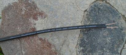
So this is the starting point for my transformer calculations:
- Transmission line impedance = 150 ohms
- Antenna impedance (guessed) of a BOG = 230-250 ohms
- Output impedance of RG6 coax= 75 ohms
Tranformer calculations and the reversing circuit
From the circuit in Fig. 7-115 of the “Low-Band DXing” book by ON4UN 5th Ed. the transformers must be calculated as follows:
T1: n1 (ant.imped.) = 250 ohms – n2 (coax imped.) = 75 ohms
T2: n1 (line imped.) = 150 ohms – n2 (coax imped.) = 75 ohms
T3: n1 (line imped.) = 150 ohms – n2 (ant.imped.) = 250 ohms
Some years ago I wrote a simple Excel spreadsheet downloadable here to quickly perform these calculations. (I am not an engineer, but it has been proven to function well for all my uses of binocular cores on low bands).

At this point I must evidence the correctness of the above drawing in the latest edition of the book. The previous ones, with a common shield connection between the coax cables, had fooled me and my reversible Beverages never worked correctly.

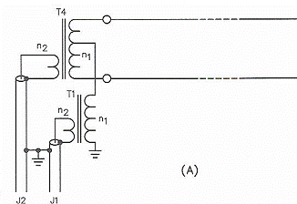
As a consequence, my first attempt was absolutely negative. My old switching box, derived from this drawing and modified here with the new transformers, was not reversing directions at all. The culprit was that common point between T4 and T1.

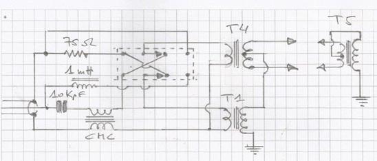
So it was necessary to use two relays to switch both sides of the transformers. The following is the corrected circuit providing full isolation between T2 and T1 and it is equivalent to use two coax cables without a shield connection between them.
By the way, as I had noted too much voltage drop of the DC relays control, I changed them from my usual OEG OMI-SH-2120 type (coil resistance 200 ohms) to smaller ones, the AXICOM V23105-A5003-A201, with a coil resistance of 720 ohms, and thus require a lot less current. Thanks Gary for advice!

Common Mode chokes
As I was out of the better FT240-31 cores, already installed on other antennas, I had to use a few FT-140A-J (75 material).
Two CMC with 8 turns of RG6 cable through 3 of these cores were inserted in the feed line with two ground rods as shown in this sketch.
The first CMC with a 1.80 m. ground rod is at the shack entrance. On the other side a small box with DC feeder, a 75 to 50 ohms transformer and another CMC wound with 5 and half turns of twisted wire through a binocular BN73-202.
The other CMC with ground rod is located at about 10 meters from the antenna feed box, where another Common Mode Choke with 5.5 turns of twisted wire through a binocular BN73-202 is inserted ahead of the relays.

Which length ?
KD9SV wrote:
….. the three “Beta Testers” for my RBOG all used 180ft of WD-1A and Carl, K9LA will be doing a write-up in NCJ magazine sept/oct timeframe about his results. I’m not sure that anybody knows the correct formula for BOG antennas length and it would be different at every location…
and K1FZ said:
I have sold many BOG antenna transformers and most customers find that 200 feet is best. But on sand, desert and other insulating earth the length can be much longer
The BOG is a tuned antenna, not like an above ground Beverage.
Oh this last sentence is really a NEW CONCEPT, but HOW to tune this antenna?
So I started with 70 meters length of wire (230 ft) with the intention to make the first measurements and tests, and then gradually reduce to reach the recommended length of 180/200 feet.
At first I checked the system with the AEA CIA antenna analyzer, and it appears to function well in both directions:
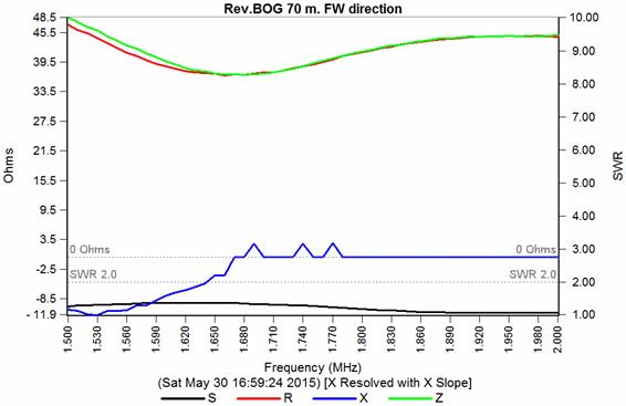
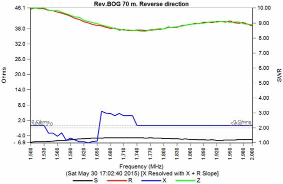
Then I began the tests with my usual 1.843 oscillator feeding a 3 m. whip.
I placed it at about 200 m. distance on the back of the BOG on one of the old ground rods which I have been unable to pull out.
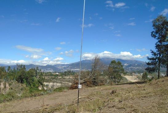
These are the readings on my SDR-IQ receiver:
- BOG to North - FWD direction: -118 dB
- BOG to South – REV direction: -103 dB
- Rot.Flag to NE direction – back: -112 dB
- Rot.Flag to SW direction - front: -108 dB
Thus the F/B is 15 dB, not exciting, but at last we are on the way and the noise level is around -120 dB, even better of the Flag.
But the first real “on the air” tests were much better. It was on Sunday morning, during the WPX CQ contest:
After scanning the band for some contest station from NA, and absolutely nothing was heard, I switched to the south and immediately a station popped out calling CQ. I couldn't believe - back to north: zero - back to south: it was LU5YF, never been able to hear before, and worked at first call.Conditions were very poor, but strange: neither W4NU nor K4IQJ were heard, but I copied VC7J as the only NA station before my SR, and that was on the BOG, nothing on the flag.
The next day I shorted the antenna wire from 70 to 65 meters, and the tests with the 1843 oscillator did not show any improvement, maybe a small lower signal and F/B. By listening on the broadcasting stations I got also the impression that the F/B was lower than the day before. Thus might it be better to go to the opposite direction, i.e. lengthen the wires?
The length of the BOG is related to the Velocity Factor of the antenna and this is depending on the local ground, and in my case it is sandy and almost desert, quite poor here, above 8.000 feet on the Andes.

At this point I did follow the DOG (Dipole on Ground) technique introduced by Guy, K2AV, to measure the velocity factor of my BOG (Beverage on Ground).
I cut in the half a76 meters wire, inserted a coax connector and put down on the ground in place of the BOG. With the AEA antenna analyzer I found its resonance point to be on 1.220 KHz. At this frequency the free space ½ wave dipole length is 123 m. (400 ft). Thus the Velocity Factor is 76/123 = 0.62. Scaling to the desired frequency of 1.825 KHz this Dipole on Ground should be only 51 meters long. But which is the parameter for the Beverage on Ground length?
This was K2AV answer:
The electrical length of an optimal bog is not a halfwave, it's somewhere around .7 or .8 wavelength, depending on what you're trying to do in the pattern. The DOG can only tell you at what frequency its electrical length is a halfwave.
So you have to scale the frequency so DOG resonance will deliver the longer length.
VF on BOGs can be anywhere between .45 and .8 depending on anything and everything.
Thus per K2AV suggested method, my BOG length should be between:
1/2 wavelength * VF * 0.7 = 540 * 0.62 * 0.7 = 233 feet (71 m.) and
1/2 wavelength * VF * 0.8 = 540 * 0.62 * 0.8 = 266 feet (81 m.).
Quite a bit longer than the 200 feet length most used in the United States…is it worth to try ? Unfortunately the band is almost dead during this season and very few stations on for tests. A few days ago my friend Dan, W5XZ, was 559 on the Flag, 579 on the RBOG – forward direction and NO copy on the reverse direction. Mario, LU8DPM was 579 on the reverse direction and NO copy on the forward direction, so for sure it’s working well, but I don’t have any idea on how broad is the lobe, until any European is coming through.
So, for now I will not make any further change and wait for better conditions, as Gary and Bruce suggested:
The BOG is a tuned antenna, not broadband like a above ground beverage. It will however work on 80 meters as near multiple of its tuning.
Yes reducing the length has moved the optimum F/B to the top of of the broadcast band and maybe above. You may be very close to the 160 meter band now, so wait and see how stations on 160 are. You will not see a front to back on anything off to the sides of the antenna.
Be careful, wait and observe front to back on stations, birdies, neighborhood noises, weather generated QRN for awhile.
73 de K1FZ
Any comment or advice to luis@iv3prk.it will be much appreciated!
June 7th 2015 Luis IV3PRK / HC1PF
Just completed a huge modeling work with EZNEC 5 and AutoEZ and the assistance of their authors, Roy Lewallen W7EL and Dan MacGuire AC6LA.
The results are very interesting and definitely my BOG length will be 63 meters.
All details and graphs on this page bog-modeling.htm
So I decided to put another BOG down towards the edge of the valley, switchable in the SW-NE directions, to cover South Pacific and Europe.




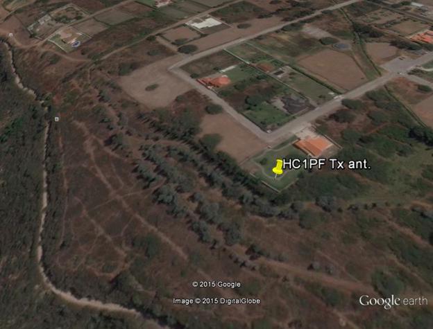
The length without any further doubt was chosen to be 63 meters with exactly the same transformers and switching boxes of the first one. I managed to hammer full down the 1.80 m. ground rods and connected to each one two 20 m. radials at right angles as in the EZNEC model.
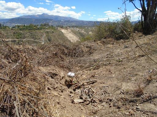
At first this new BOG was working well in the forward direction, but not on the reverse: the switching circuit was ok, but the signal was about 30 dB down. Finally, after checking and rechecking I found the culprit in the far end box: an error in the xfmr connections!
Unfortunately the band conditions are so poor these days with low activity, but enough to carry on the desired tests. The results are very good with 20 to 30 dB of F/B and always better than the rotatable flag. The noise level is lower and signal is sufficient to let my second preamplifier off: 10 dB of preamp gain is enough with both BOGs.
At last I managed to find the solution to all my receiving problems with four directions quickly switchable with the two Reversable BOGs, but this system survived for a short time: the telephone wire making the second BOG was discovered and stolen, only 12 dollars of value, but that was enough (3rd time) to take a decision …I recovered the switch/transformer boxes and now packing everything to go back home in Italy.
Really anxious to test and see how these Rev.BOGs work in a different environment!
Quito, July 2 2015 Luis HC1PF / IV3PRK
